Many people who draw PCB think that silk screen does not affect the performance of the circuit, so they don't pay much attention to silk screen. However, for a professional hardware engineer, these details must be paid attention to.
1. Placement Position
Generally speaking, when placing the silk screen of resistors, capacitors, tubes and other components, do not use four directions. This will cause the screen printing to be very tired when debugging, repairing, and welding (the board needs to be turned in several directions).
Therefore, it is recommended to place them in two directions, as shown in the figure below. In this way, it will be very convenient to check the silk screen.
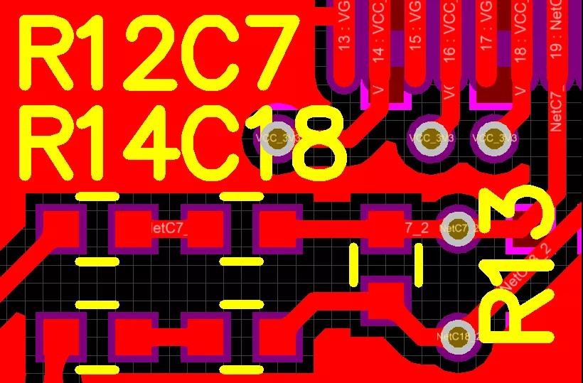
As shown in the figure below, if the components are too dense to fit the silk screen, you can write the silk screen in a blank place nearby, mark the arrow, and it is best to draw a frame, so that it is easier to identify.
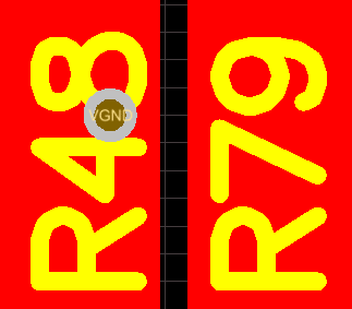
2. Try not to punch the vias on the silk screen
As shown in the figure below, the via hole is punched in the figure of 8. After punching the board, you will not be able to tell whether it is R48 or R49.
3. Do not press the silk screen on the high-speed signal line
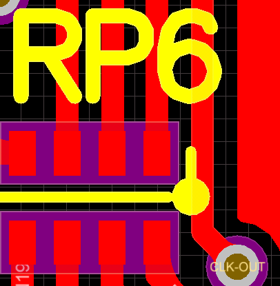
This recommendation is for high-speed signal lines on the top or bottom layer, because this type of signal line can be regarded as a microstrip line.
The speed (phase speed) of the signal on the microstrip line is related to the medium. If the silk screen is pressed to the line, as shown in the figure below, the medium will become uneven, resulting in a change in the phase speed, which ultimately shows a discontinuous impedance, affect the signal quality.
Of course, there will be no such problem in the signal line of the inner electric layer.
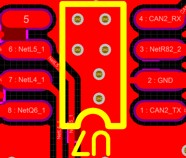
4. The reading direction of the silk screen should be consistent with the direction of use
As shown in the figure below, the reading direction of the silk screen is the same as the using direction of the chip, which is mainly used to reduce the probability of reverse soldering when soldering.
Others, such as electrolytic capacitors, etc., can also not follow this recommendation, because you can indicate the positive and negative polarity.
5. The pin number should be clearly marked on the silk screen
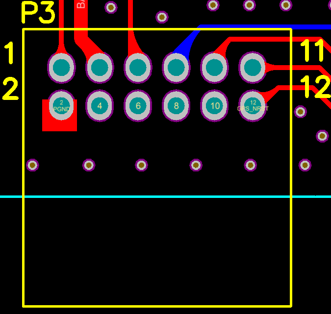
As shown in the figure below, 4 pin numbers are marked on the P3 connector to facilitate debugging/installation. In addition, it is best to mark the places where the pins are dense, such as chips, FPC sockets, etc.
At the same time, it also complies with the previous suggestion. The reading direction of P3 is consistent with the direction of use of the connector.
6. Silk screen for special packaging
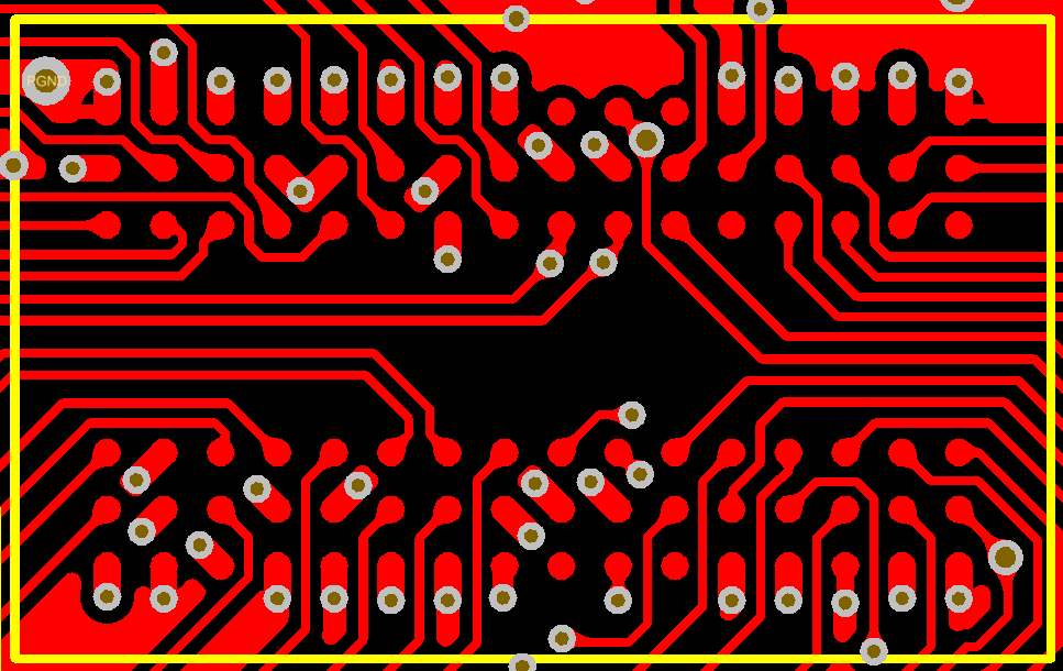
For special packages such as BGA and QFN, the size of the silk screen must be exactly the same as the size of the chip (as shown in the figure below), otherwise it will be difficult to align, which will affect the soldering.
7. The silk screen of the mounting hole
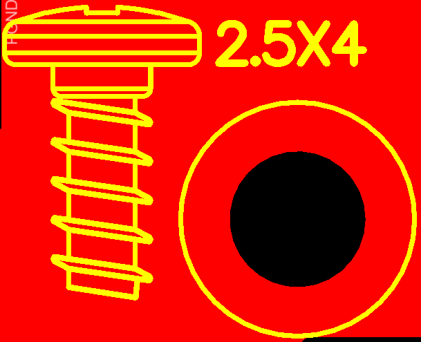
Here, the silk screen of the screw is added near the installation hole, and the length and the total number of screws are also indicated, which is convenient for installation.
8. The ambiguity of silk screen
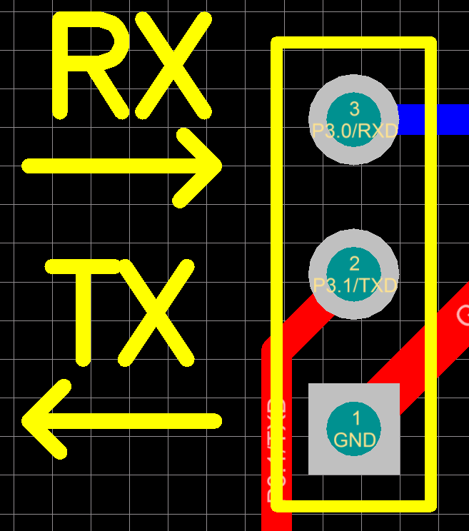
The most commonly used RS232, many people will label RX and TX, but there are also RX and TX on the PC side, when to use a crossover cable and when to use it?
This leads to the ambiguity of the silk screen, which makes people foolishly confused.
Two arrows are added here to show the direction of the indicator signal (as shown in the figure below), so that you can know how to wire it at a glance.
Not only RS232 can do this, other, such as: SPI, etc., with transmit and receive signal lines, can do so.
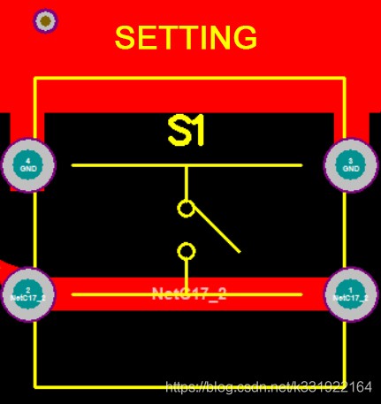
9. Mark the function
Some user-used components, such as buttons, lights, knobs, etc., need to be written with functions and uses. As shown in the figure below, the button is the setting button and the light is the status indicator.
10. Add LOGO
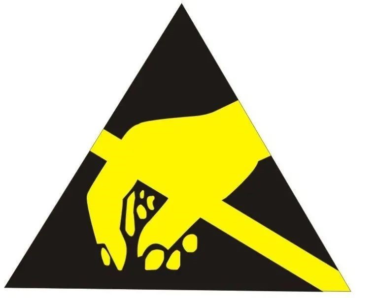
If there is space, you can add the company's LOGO, anti-static logo, one-dimensional code, and two-dimensional code on the board.
If there is certification, the certification LOGO should be added.

There are heating elements, and high temperature signs can be added.
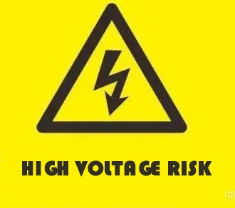
There are high-voltage components, and high-voltage signs can be added.


 whatsapp